Every board tested, diagnosed and sorted by a Cobot
The Cobot loads each board onto your tester, adds a camera check for visible faults, and hands your technician one clear fault report. The same steps as a person doing it by hand, just faster and the same every time.
Illustrative pilot baseline: ~240 boards per shift · under 2 seconds handling per board · 1 technician overseeing 3 cells. Your numbers are measured during the pilot.
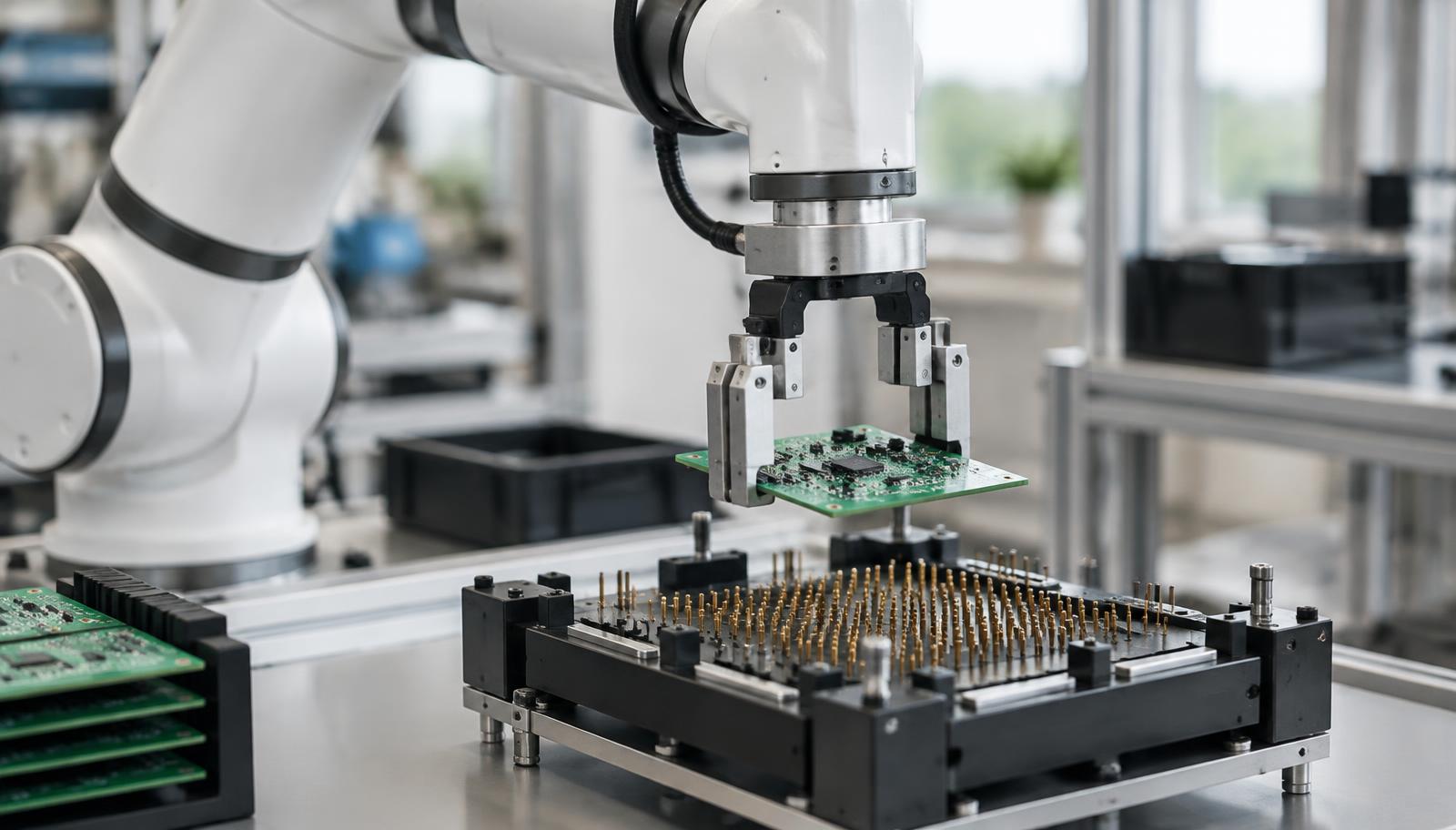
Automated ICT / FCT fixture handling with a Cobot
Four steps per board, running without breaks.
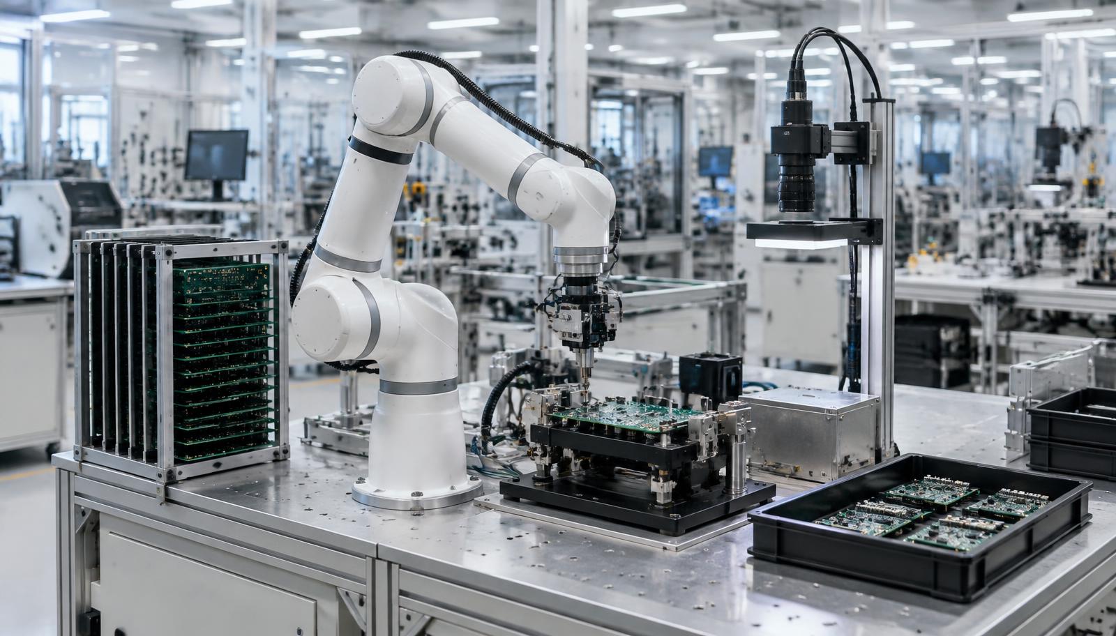
The Cobot takes each board from the rack by its edges and seats it on the test fixture.
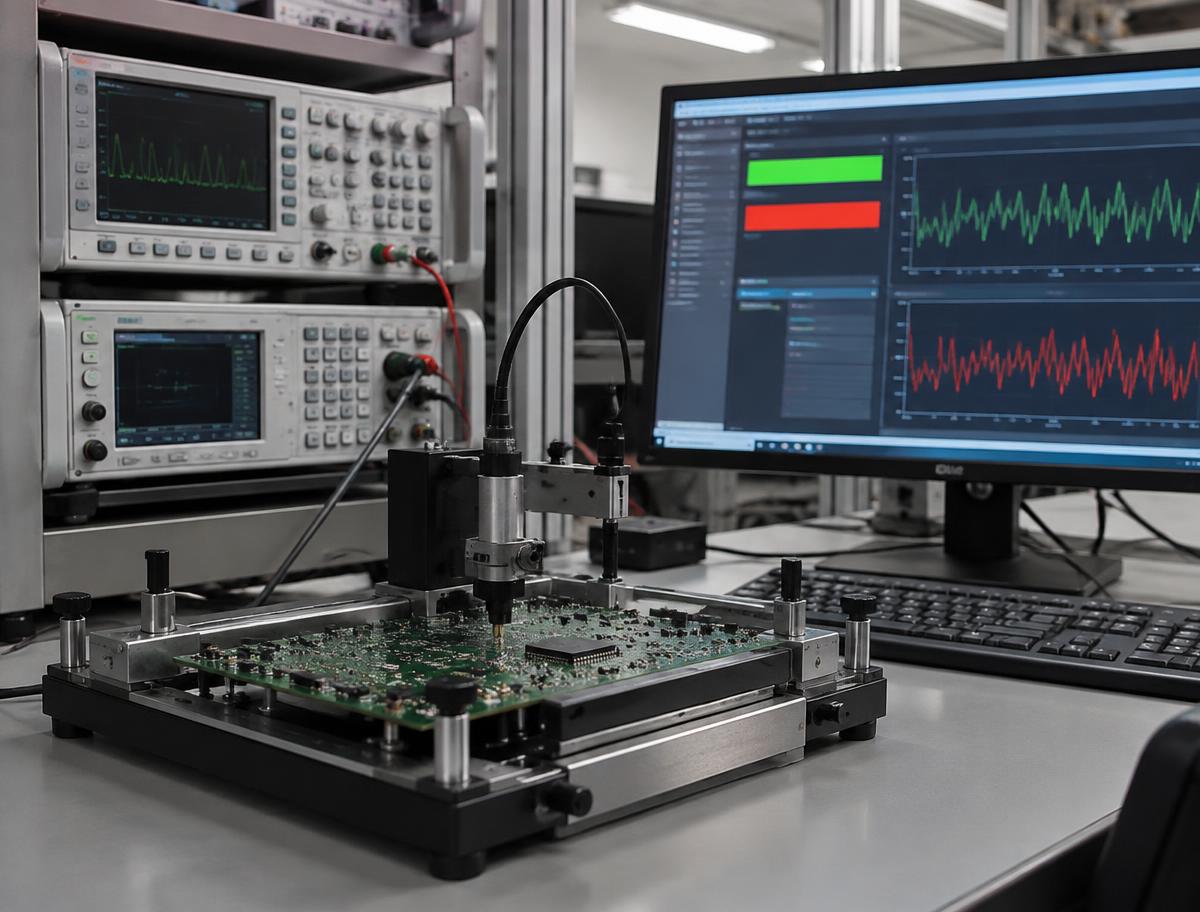
A connected tester, run by a computer, checks power-on, voltages and currents, boundary-scan and firmware.
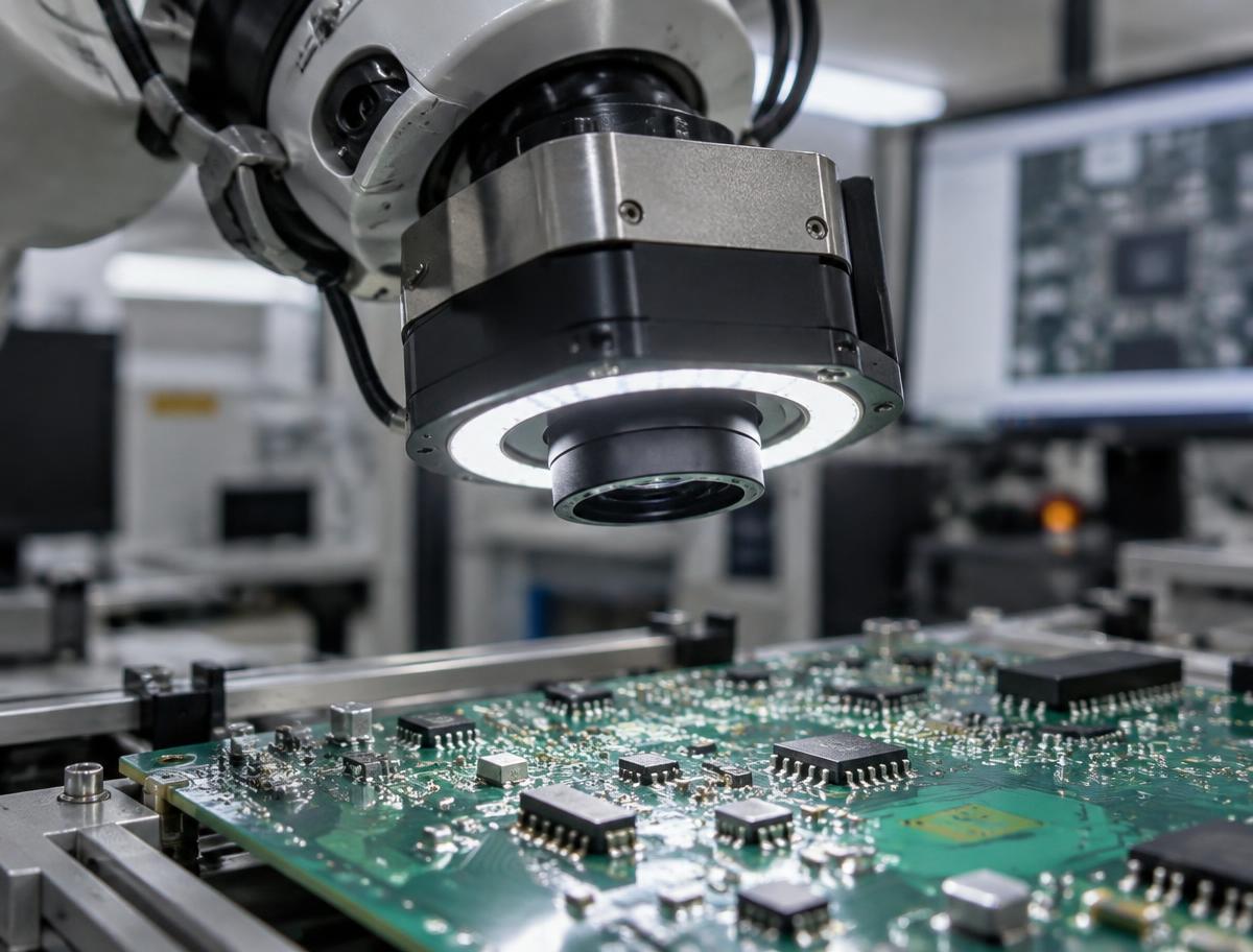
Once the arm has settled, a camera checks for visible faults: solder bridges, missing, tilted or reversed parts, cold joints, burn marks.
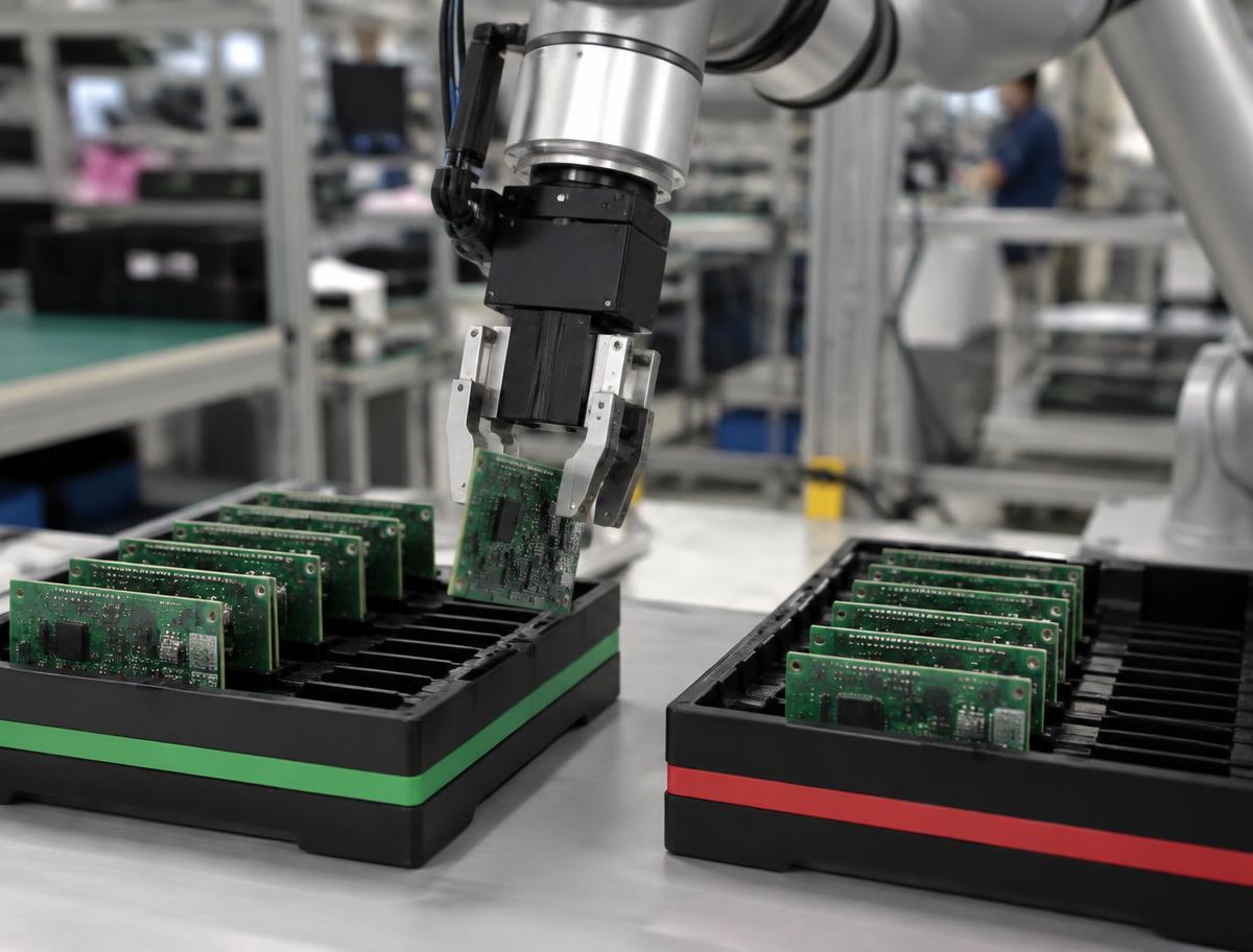
Tester results and the image are combined into one fault report with the likely location. The board goes to the pass or fail tray.
What the cell checks
Visible faults (camera)
- Solder bridges and cold joints
- Missing, tilted or reversed parts
- Burn marks and damaged areas
- Wrong or misplaced components
Electrical faults (tester)
- Power-on and short checks
- Voltage and current out of range
- Boundary-scan (JTAG) failures
- Firmware load and self-test results
What we don't claim
- No 100% promise. Coverage depends on the fixture and test program for each board, and we state it per project.
- Engineers stay in charge. The cell does the repetitive testing and diagnosis. Your technician does the repair.
- Soldering by Cobot is on request only, after a separate safety review.
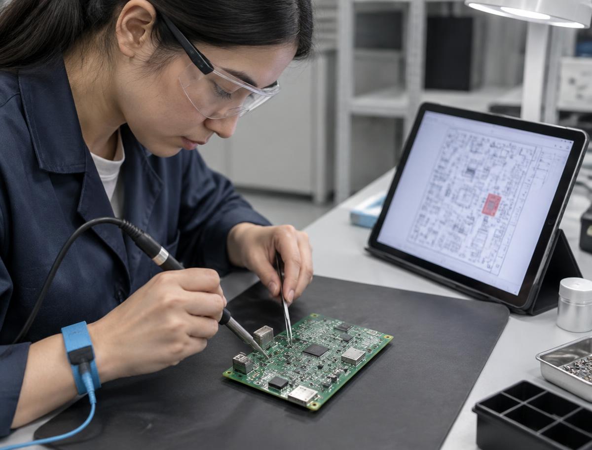
Your technician only does the repair
Each failed board arrives with a report: which test failed, the camera image and the likely location. No more hunting for the fault. Skilled people spend their time fixing boards instead of testing them.
Built for
- Electronics assembly companies (EMS)
- Repair and refurbishment centres
- Test labs and product makers running pilot batches
Example fault report
What your technician receives for every failed board. Sample data for illustration.
How it connects to your line
The Cobot uses your existing tester and fixture; we add handling, vision and reporting.
- 1Board input rack
- 2Cobot load
- 3Test fixture + your ICT/FCT
- 4Camera inspection
- 5Pass / fail sort
- 6Fault report to technician + MES
Technical specifications
Typical ranges; final values are confirmed in the feasibility check with your boards.
Payback calculator
Enter your own numbers (HK$). This is an estimate, not a quote.
Real deployments by other companies: industry case studies (third-party examples, not SMERT projects).
How we work together
About 1 week with 5 of your sample boards and your current tester.
Built for your board and quoted per project, typically 2–4 weeks.
The cell runs on your line and we measure the results together.
24/7 remote support and technicians in APAC, EU and the Americas.